Team Project 2: Shop Show
A miniature kinetic sculpture showcasing replica shop machines, powered by a single DC motor with an interconnected chain system that demonstrates the unique fabrication capabilities of Olin College.
Design Process:
Initial Concept
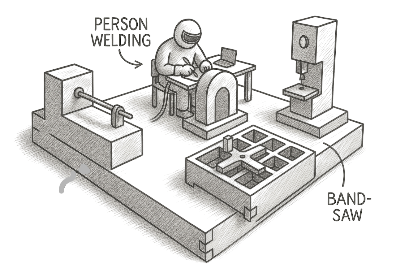
Our inspiration came from Olin's extensive shop facilities, which are unusually comprehensive for a small college. We chose to highlight five key machines (bandsaw, disc sander, lathe, plasma cutter, and welder) that represent the breadth of fabrication capabilities available to students.
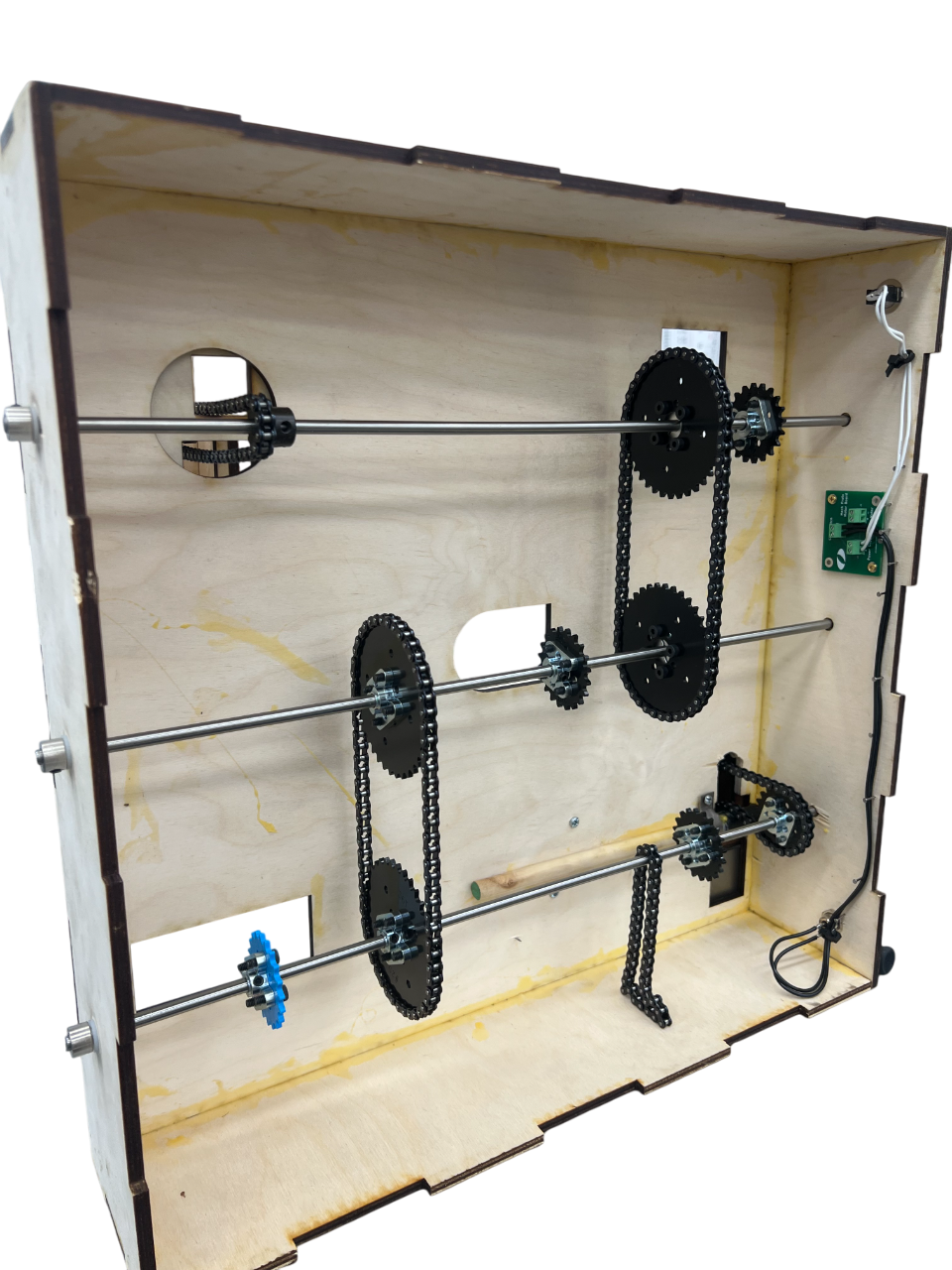
Early design ideas focused on creating miniature working replicas that would capture the essence of each machine's movement. The concept evolved to utilize a single motor driving three interconnected shafts, with each machine mechanism connecting to one of these shafts through chains.
Prototyping
What We Prototyped:
Lathe, belt sander and bandsaw using a basic chain and 2 sprocket system.
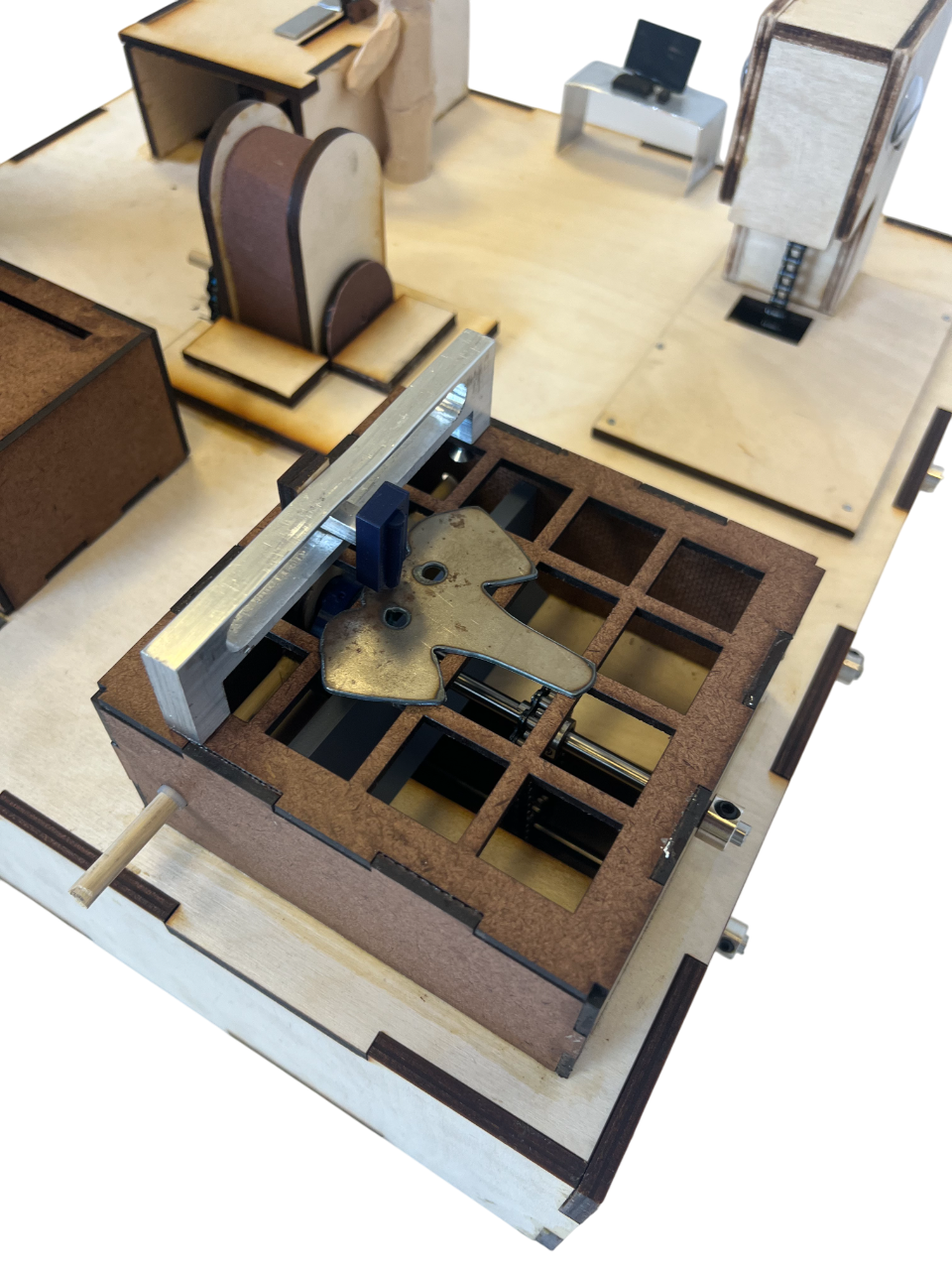
Plasma Cutter with Scotch Yoke mechanism to explore the moving plasma head flutter motion.
Welder with Scotch Yoke mechanism to explore the alternating weld gun motion to achieve good welds.
What We Learned:
Box dimensions were dialed in to balance space for all mechanisms without overcrowding
Joint tolerance and alignment are critical—loose fits caused jamming or wobble
Assembly steps became clearer, helping us plan for modular sub-assemblies

CAD Development
The CAD model refined the design through:
Precise part integration: Ensured that all mechanical elements—windmill, flower linkages, butterfly yoke, bunny cam, and chick lifter—fit within the confined box space without collisions.
Motion simulation: Enabled virtual testing of each mechanism's motion path and range before fabrication, reducing risk of failed assembly.
Belt and pulley layout: Optimized pulley spacing, shaft alignment, and belt tensioning for consistent motion transfer across four vertical axes.

3. Material and Manufacturing Constraints
Challenge: Sheet metal components had specific manufacturing limitations that affected design possibilities, particularly for the plasma cutter and welder parts.
Solution: We leveraged multiple manufacturing methods to overcome limitations. Where sheet metal couldn't be easily formed, we substituted laser-cut wood with appropriate joints. For complex three-dimensional forms, we integrated 3D printed components. This hybrid approach allowed us to maintain design integrity while working within the constraints of available materials and manufacturing techniques.
Technical Challenges & Solutions
1. Scotch Yoke Friction Issues
Challenge: The initial plasma cutter scotch yoke design did not work as planned due to excessive friction in the mechanism.
Solution: We redesigned the sliding components with looser tolerances and smoother surfaces, and added lubricant at contact points. We also modified the material and geometry of the connection points to reduce binding. These changes significantly improved the motion smoothness without requiring complete redesign of the mechanism.
Objective of the Design Project:
To design and fabricate a working miniature sculpture that represents five key shop machines from Olin's extensive facilities. The project needed to:
Feature scaled replicas of bandsaw, disc sander, lathe, plasma cutter, and welder
Convert rotational motion from a single 25 RPM DC motor to power all machines
Utilize various motion mechanisms including rotational-to-rotational and rotational-to-translational
Incorporate multiple manufacturing techniques showcasing Olin's fabrication capabilities
Create an educational and visually engaging display piece that celebrates Olin's unique shop resources
Skills Developed and Practiced:
CAD Modeling & Assembly Design
Designed complex multi-part systems with motion constraints and mechanical integration.Chain Drive Systems
Implemented shaft-driven mechanisms with interconnected power transfer between components.Motion Mechanism Design
Engineered both rotational-to-rotational and rotational-to-translational motion systems including scotch yoke mechanisms.Laser Cutting
Fabricated precise flat components with tight tolerances for mechanical assemblies.3D Printing
Created complex shaped components and functional tools with additive manufacturing.Lathe Work
Machined custom spindles and turned cylindrical components for the lathe and plasma cutter.Plasma Cutting
Produced metal components with complex shapes including the elephant design and platform.Mechanical Assembly
Integrated multiple complex sub-assemblies into a coherent, functional whole.Design for Manufacturing
Balanced design requirements with fabrication constraints for efficient production.Team Leadership
Divided tasks effectively between team members and helped teach members how to do things.
Results
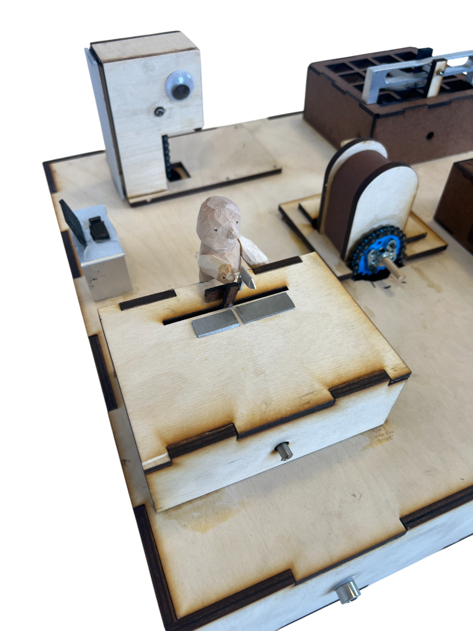
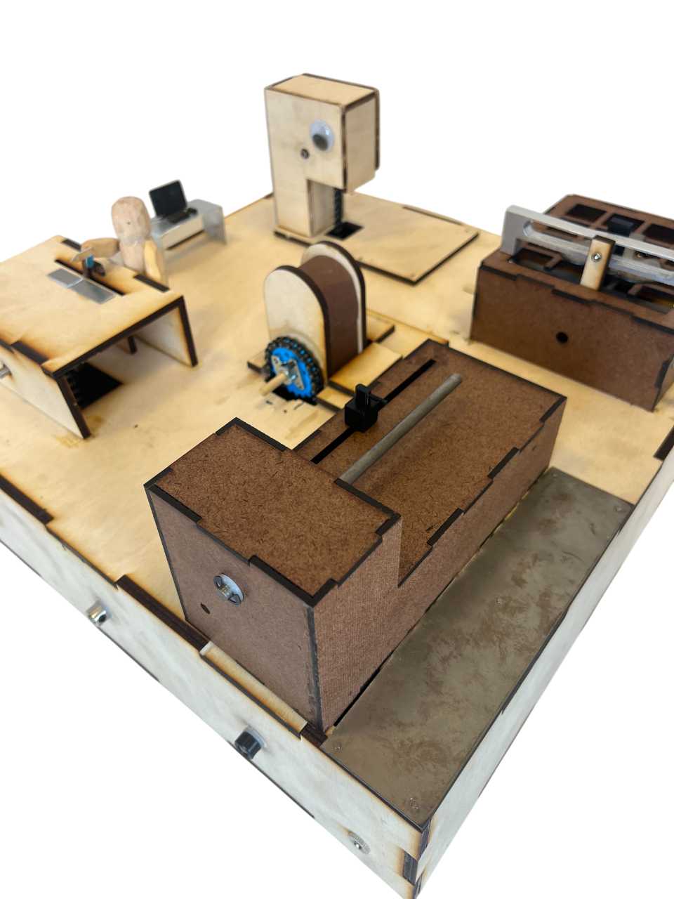
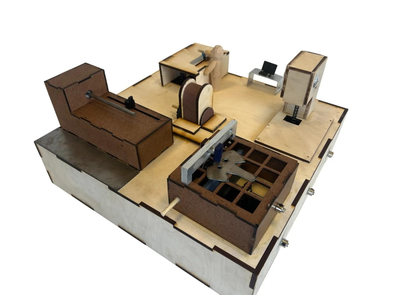
Our final Mini Olin Shop successfully represents five shop machines in a compact, functional display. Each component demonstrates specific mechanical principles:
The bandsaw shows rotational motion with the chain mimicking the blade movement
The disc sander features a rotating disc surface with accurate representation of the machine
The lathe includes a turning spindle with a sliding tool rest
The plasma cutter demonstrates precise linear movement with its torch following a controlled path
The welder features a figure that moves realistically while "welding" sheet metal parts
The integration of multiple manufacturing techniques—including laser cutting, 3D printing, turning on a lathe, and plasma cutting—demonstrates the breadth of fabrication capabilities that inspired the project. The single motor powers all mechanisms through an elegant chain system, creating a cohesive kinetic sculpture that successfully meets our design objectives.
What we're most proud of is how the project serves as both an engaging kinetic sculpture and an educational tool that showcases different motion mechanisms and manufacturing techniques in a visually interesting way.
2. Chain Routing Challenges
Challenge: Positioning holes for chains to correctly route through to drive mechanisms proved difficult, with initial placements causing chain misalignment and binding.
Solution: We created precise test templates to verify hole positions before cutting final parts. By carefully mapping the 3D path of each chain and calculating the exact entry/exit points, we ensured proper alignment. This attention to detail in chain routing was critical for achieving smooth, reliable operation of all five mechanisms.